


CMOS (complementary metal oxide semiconductor) is a special type of memory (64K) used to hold crucial system operation information called the BIOS (basic input/output system). The instructions it holds are permanently written to the chip. The CMOS needs very low power to operate. It is recharged every time the computer is turned on. Most modern boards do not use batteries. The time and date is kept by the CMOS. The type of CMOS does not effect the performance of the system.
BIOS is a program that manages data flow between the operating system and attached devices such as the clock, hard disk, ram, video adapter, input/output devices and power management. It is an integral part of your hardware. The BIOS is accessible to the microprocessor on an erasable programmable read-only memory (EPROM) chip. When you turn on your computer, the microprocessor passes control to the BIOS program, which is always located at the same place on EPROM.
When BIOS boots up your computer, it first determines whether all of the attachments are in place and operational and then it loads the operating system. Some BIOS setting can be changed from inside the operating system such as the time and date. The BIOS inside a personal computer determines whether the date will handle the year 2000 correctly. The three leading BIOS manufacturers are AWARD, Phoenix and AMI (American Megatrends).
Introduction
Next to the CPU, the BIOS is the most important chip found on the motherboard. A firmware device, the BIOS provides vital services at bootup, hardware standards for your system and, through its configuration utility, many ways to customize your system. To understand the differences between hardware, software, and firmware, see "The Essential Parts of Any Computer".
The BIOS (Basic Input Output System) chip performs a variety of important tasks during system operation. On systems that use 32-bit versions of Microsoft Windows (Windows 95 or newer), the BIOS has relatively little to do with system operation after the boot process has been completed. However, during the boot process, the BIOS is an extremely critical component. Tasks that the BIOS chip performs include
- Configuration and control of standard devices
- The power-on self test (POST)
- The location of an operating system, to which it turns over control of the system by using the Bootstrap loader
The CMOS (Complementary Metal-Oxide Semiconductor) chip stores the settings that you make with the BIOS configuration program. The BIOS offers you many different options for most system components controlled by the BIOS, but until the settings are stored in the CMOS, the system is unable to run.
The BIOS and Standard Devices
The BIOS is a complex piece of firmware ("software on a chip") that provides support for the following devices and features of your system:
- Selection and configuration of storage devices, such as hard drives, floppy drives, and CD-ROM drives
- Configuration of main and cache memory
- Configuration of built-in ports, such as IDE hard disk, floppy disk, serial, parallel, PS/2 mouse, and USB
- Selection and configuration of special motherboard features, such as memory error correction, antivirus protection, and fast memory access
- Support for different CPU types, speeds, and special features
- Support for advanced operating systems, including networks, Windows 9x, and Windows 2000 (Plug and Play)
- Power management
Storing System Settings:
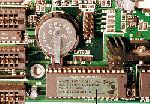
To enable the BIOS to perform these tasks, two other components on the mother- board work with the BIOS: the CMOS chip, also known as the RTC/NVRAM (Real-Time-Clock/Non-Volatile RAM), and the battery. The CMOS stores the settings that you make with the BIOS configuration program and contains the system's Real-Time-Clock circuit. Power from a battery attached to the motherboard is used by the CMOS to keep its settings. Figure 3.1 shows a typical socketed BIOS and battery. The A+ Certification test might ask you to identify these devices on a motherboard and to explain their operation.
Figure 3.1
The CR2032 battery has become the most common removable battery on Pentium-class
systems. The Award BIOS label lists support for "586" (Pentium-class)
CPUs, PnP (Plug and Play for Windows 95), and PCI slots.
Most recent systems use various models of lithium batteries, which can last from two to five years. Figure 3.2 shows three of the many battery types used on motherboards over the years.
The most common batteries you will see in Pentium-class and newer systems are the DS12887A-type clock/battery chip seen in Figure 3.2 (left) and the CR-2032 lithium battery seen in both Figure 3.1 and Figure 3.2 (center). The AA-size Eternacell in Figure 3.2 on the right was used in many early 286- and 386-based systems made by Zenith Data Systems and others. Knowing that battery types can vary is not as important for the A+ Certification test as it will be for your day-to-day work.
Figure 3.2
The Dallas Semiconductor DS12887A (left) clock/battery chip, CR-2032 lithium
battery (center), and the AA-size 3.6 volt Eternacell (right) have all
been used in computers for maintaining CMOS settings.
When the battery starts to fail, the clock will start to lose time. Complete battery failure causes the loss of all CMOS configuration information. When this takes place, the system cannot be used until you install a new battery and re-enter all CMOS configuration information by using the CMOS configuration program.
Because the battery maintaining settings can fail at any time, and viruses and power surges can also affect the CMOS configuration, you should record important information before it is lost. See "Saving and Recording BIOS/CMOS Settings," later in this chapter, for details.
POST
The POST (power-on self test) portion of the BIOS allows the BIOS to find and report errors in the computer's hardware. For the POST to work correctly, the system must be configured correctly, as you will see in "System Configuration," later in this chapter.
The POST checks the following parts of the computer:
- The CPU and the POST ROM portion of the BIOS
- The system timer
- Video display card
- Memory
- The keyboard
- The disk drives
The system will stop the boot process if it encounters a serious or fatal error (see the following "Beep Codes" section). During the POST process, the BIOS uses any one of several methods to report problems:
- Beep codes
- Onscreen error messages
- POST error codes
Beep Codes
Beep codes are used by most BIOS versions to indicate either a fatal error or a very serious error. A fatal error is an error that is so serious that the computer cannot continue the boot process. A fatal error would include a problem with the CPU, the POST ROM, the system timer, or memory. The serious error that beep codes report is a problem with your video display card or circuit. Although systems can boot without video, seldom would you want to because you can't see what the system is doing.
Beep codes vary by the BIOS maker. Some companies, such as IBM, Acer, and Compaq, create their own BIOS chips and firmware. However, most other major brands of computers and virtually all "clones" use a BIOS made by one of the "Big Three" BIOS vendors: American Megatrends (AMI), Phoenix Technologies, and Award Software (now owned by Phoenix Technologies).
As you might expect, the beep codes and philosophies used by these three companies vary a great deal. AMI, for example, uses beep codes for over 10 "fatal" errors. It also uses eight beeps to indicate a defective or missing video card. Phoenix uses beep codes for both defects and normal procedures (but has no beep code for a video problem), and the Award BIOS has only a single beep code (one long, two short), indicating a problem with video.
Because beep codes do not report all possible problems during the startup process, you should not rely exclusively on beep codes to solve system problems.
You can hear some typical beep codes by using the CD-ROM included with this book.
Onscreen Error Messages
Most BIOS versions do an excellent job of giving you onscreen error messages indicating what the problem is with the system. These messages can indicate problems with memory, keyboards, hard disk drives, and other components. Some systems document these messages in their manuals, or you can go to the BIOS vendors' Web site for more information. Keep in mind that the system almost always stops after the first error, so a serious problem early in the boot process will stop the system before the video card has been initialized to display error messages.
POST Codes and POST Cards
In Chapter 1, "Basic Concepts," you learned about the different ways data passes through the system. One method, used by virtually all devices, is to send data through one of 65,535 I/O port addresses. The POST also uses an I/O port address (usually 80h), sending a series of codes indicating the progress of testing and booting. The hexadecimal codes output by the BIOS change rapidly during a normal startup process as different milestones in the boot process are reached. These codes provide vital clues about what has gone wrong when your system won't boot and you don't have a beep code or onscreen messages to help you.
To monitor these codes, you need a POST card such as the one shown in Figure 3.3, available from a variety of vendors, including JDR Microdevices (http://www.jdr.com) or Jensen Tools (http://www.jensentools.com). These cards are available in versions that plug into either ISA or PCI expansion slots. The simplest ones have a two-digit LED area that displays the hex codes, whereas more complicated (and expensive) models also have additional built-in tests.
The same hex code has different meanings to different BIOSes. For example, POST code 31h means "display (video) memory read/write test" on an AMI BIOS, but it means "test base and extended memory" on the Award BIOS, and it is not used on Phoenix BIOS. As with other types of error messages, check your manual or the BIOS maker's Web site for the meaning of any given code.
Figure 3.3
The Ultra-X PC Inspector card features POST display (1), DMA conflict
detection (2), and IRQ conflict detection (3) among its many features.
The best way to learn to use a POST card is to plug it into a healthy system and watch the codes change during a normal system startup. Typically, the codes change very quickly until the final code (often "FF") is reached and the system starts. On a defective system, the codes will pause or stop when a defective item on the system is tested. The cards remove easily and need not be left in systems routinely.
To prepare yourself for the A+ Certification exam, make sure you can identify the three different methods computers use for identifying errors (beep codes, onscreen codes, and POST codes) and when each method is most appropriate for discovering why a computer cannot boot.
Transferring Control to the Operating System with the Bootstrap Loader
During the POST, drives and other standard devices have been detected. Frequently, information about the CPU, hard disk, floppy disk drive, memory size and type, and ports are displayed onscreen at the end of the POST (see Figure 3.4).
Figure 3.4
A typical Pentium-based system configuration screen displayed on system
startup. Use this information for a quick view of the system's features,
including CPU type and speed, RAM size and type, drive configuration,
and more.
Next, the BIOS searches for an operating system on the drives listed in the BIOS configuration as bootable drives. The first drive containing an operating system will be used to start the computer, and at that point the BIOS transfers control of most of the computer to the operating system. The portion of the BIOS responsible for starting the system is called the bootstrap loader (from the old expression "pulling yourself up by your bootstraps").
For a more detailed look at how the startup process works after the BIOS locates the operating system, see Upgrading and Repairing PCs, 12th Edition, Chapter 25, "The Hardware Boot Process."
Warm and Cold Booting
A cold boot or hard boot refers to starting the computer with the power or reset switch, which runs the entire POST and bootstrap process. A warm boot or soft boot skips the POST and refers to restarting the computer with the MS-DOS Ctrl+Alt+Del key sequence or the Windows 9x/2000 Start, Shutdown, Restart menu. Figure 3.5 shows a typical screen displayed during a cold boot.
Figure 3.5
The screen during a cold boot. Note the memory test at the upper-left
side.
On an MS-DOS–based system whose hard disk and floppy disk drives are connected to the motherboard, the BIOS is used to operate the drives. However, for systems using Windows 95 and newer, device drivers are loaded by the operating system to replace the BIOS. Still, without the BIOS, the system would not know what hardware was onboard or whether it was working.
System Configuration
For the BIOS to be able to start the computer, you've seen that it must find an operating system on a hard disk or floppy disk drive. But how does the BIOS know where the drives are located or what types they are?
Floppy disk drives and hard disk drives are two of the most important items that must be configured in the BIOS. If the drive types are not correctly identified in the BIOS, the BIOS will not be able to start the system. Whenever you build a system or change major components, you need to run the BIOS setup program to check or change settings.
Starting the Setup Program
On most systems built since the late 1980s, the BIOS configuration program is stored in the BIOS chip itself. On a few current systems, as with the original IBM AT, the setup program must be run from a floppy disk drive or the hard drive. The original IBM PC and PC/XT had only a few settings, and these were made by manipulating a series of small rocker or slide switches called DIP switches.
ROM-based setup programs are normally started by pressing one or more keys in combination within the first few seconds after turning on the computer. Although these keystrokes vary from system to system, the most popular keys on current systems include the escape (Esc) key, the Delete key, the F1 key, and various combinations of Ctrl+Alt+ another specified key. Most computers display the correct key(s) to press during the initial startup screen. Check with your system vendor for the appropriate keystrokes or to see if you need to run a program from MS-DOS or Windows to configure your system.
Because the settings you make in the BIOS setup program are stored in the nonvolatile RAM of the CMOS chip, the settings are often called CMOS settings.
In the following section, we will review the typical setup process, looking at each screen of a typical Pentium-class system.
Step-by-Step CMOS/BIOS Configuration
The A+ Certification exam will test your knowledge of basic CMOS/BIOS configuration. To help you prepare for the exam, this section covers the most important portions of the CMOS/BIOS setup process.
To start the CMOS setup process, press the correct key(s) during the bootstrap process or run the setup program from hard disk or floppy disk after the computer has started. On virtually all systems built since the early 1990s, you'll start with a menu screen, as shown in Figure 3.6. This menu, as well as the contents of the screens listed, will vary according to your BIOS brand, version, and motherboard type.
Figure
3.6
Select the menu item from this CMOS Setup menu to examine or change settings.
Select Standard CMOS Setup to begin.
Other systems will immediately display the Standard CMOS Setup screen, which is typically used to configure drive, date, and time settings.
Standard CMOS Configuration
The standard CMOS configuration screen (see Figure 3.7) includes settings for items such as
- Date
- Time
- Floppy disk drive types for drives A: (first floppy disk drive) and B: (second floppy disk drive)
- Hard drives connected to the IDE interface
Figure
3.7
A typical standard setup screen. On this system, hard drives can be detected
during the boot process ("Auto" setting), but they can also
be user-defined, as shown here.
To make selections here, you normally press keys to cycle through the different options, including date and time.
The time must be entered in the 24-hour format (1:00PM = 13:00, and so on). Enable daylight savings unless your state or area (Arizona, Hawaii, and parts of Indiana) doesn't switch to DST in the spring and summer.
Change the default floppy drive types to match your current configuration if necessary. See "Floppy Disk Drives," page 191, for details on selecting the correct floppy disk drive type.
To select the correct hard drive type, you can use one of three methods:
- Manually enter the correct settings.
- Use an auto-detection feature located here or from the main menu.
- Allow the system to detect the hard drives during every system boot.
Some systems also display the amount of memory onboard on this screen, but only extremely old systems based on 386 or older processors require that you manually enter the amount of RAM in the system. On virtually all systems using a 286 processor or better, the standard CMOS configuration screens are extremely similar, varying mainly in the number and types of drives that can be used.
The standard setup screen is the single most important screen in the entire BIOS/CMOS setup process. If the drives are not defined correctly, the system cannot boot.
Automatic Configuration of BIOS/CMOS Settings
Many versions of the AMI and Award BIOS allow you to automatically configure all screens except the Standard setup screen with a choice of these options from the main menu:
- BIOS Defaults (also referred to as Original/Fail-Safe on some systems)
- Setup Defaults (also referred to as Optimal on some systems)
- Turbo
Use BIOS defaults to troubleshoot the system because these settings are very conservative in memory timings and other options. Normally, the Setup defaults provide better performance. Turbo, if present, speeds up the memory refresh rate used by the system. As you view the setup screens in this chapter, you'll note these options are listed. If you use either automatic setup after you make manual changes, all your manual changes will be overridden!
Appropriately, the graphical AMI WinBIOS uses a tortoise, a hare, and an eagle for these three options.
With many recent systems, you can select Optimal or Setup Defaults, save your changes, and exit, and the system will work acceptably. However, you might want more control over your system. In that case, look at the following screens and make the changes necessary.
Advanced CMOS Configuration
The advanced CMOS configuration screen, shown in Figure 3.8, allows you to adjust optional details about the computer. In this screen, you can adjust the NumLock setting, type of video, keyboard repeats speed, settings for cache memory, and other special features. Most systems built since the early 1990s include this screen.
Figure 3.8
A typical Advanced CMOS Configuration screen, also known as the BIOS Features
screen—use this screen to enable or disable anti-virus hardware features,
adjust boot sequence, and adjust memory options such as cache and parity
checking.
Table 3.1 lists the most important options and my recommendations.
Table 3.1 Recommended Advanced CMOS Settings
| Option | Setting | Reason |
| Write-Protect Boot Sector, Virus Warning, or Antivirus Protection | Enable for normal system use | This doesn't really stop viruses, but it will help prevent users from accidentally FORMATting or FDISKing the hard disk. |
| Cache Internal | Enabled | Cache memory makes system faster (see and External"Adding Main and Cache RAM," page 54. |
| Boot Sequence | C: (first hard disk), A: (floppy disk drive), CD-ROM, C:, A: | Prevents users from booting with floppy floppy disk left in A: won't spread disks; boot sector viruses to the system; system won't stop if floppy disk is left in A:. |
| Shadowing | Enable for memory addresses containing firmware (BIOS) chips | Copies firmware contents such as system BIOS, video BIOS, and add-on card BIOS to RAM. Located between 640KB-1MB (upper memory blocks). |
| LBA mode | See "Overcoming Hard Disk Capacity Limitations with LBA Mode," |
Depending on the system, you might be able to boot from CD-ROM, ZIP, or LS-120 drives in addition to the floppy disk drives and hard drives traditionally available as boot devices, as shown in Figure 3.9.
Depending on the BIOS version, you might need to press the ESC key, as in Figure 3.9, to return to the main menu, or use cursor keys to move directly to another menu screen.
Figure 3.9
This recent Pentium-class system offers a variety of boot options. To
view the settings for any CMOS configuration option, either use the help
key (F1) as shown here, or press the correct key to step through the options
for the setting.
Advanced Chipset/Chipset Features Configuration
The Advanced Chipset/Chipset Features Configuration screen, like the one shown in Figure 3.10, offers many advanced options that vary by the system. The following are some typical features of this menu:
- Memory types, speed and timing—Adjust the values here to match the memory installed in the system (such as parity, non-parity, SDRAM, EDO, and so on).
- Cache adjustments—Some Cyrix CPUs require the user to disable pipelining for proper operation.
- Configuration of USB ports—If you upgrade a system to Windows 98 or Windows 2000, you might need to enable the USB ports; systems with older versions of Windows (which didn't support USB) might not have the USB ports enabled. The USB Keyboard Support feature must be enabled if a USB keyboard is installed to allow the keyboard to operate outside of Windows.
- Configuration of the AGP slot—Depending on the specific AGP video card installed (if any), you might need to set the size of the memory aperture used to transfer data between the system and the AGP port and select the AGP mode (1x, 2x, and 4x).
Figure 3.10
This recent system's USB (Universal Serial Bus) and AGP (Advanced Graphics
Port) options are located on the Chipset Features configuration screen,
along with the usual system and memory-timing options.
Power Management Configuration
Virtually all systems built since the mid-1990s are designed to allow power management; watch for the EPA "Energy Star" logo when you start the computer.
Power management works like this: After a user-defined period of inactivity, devices such as the monitor, the hard drive, or even the CPU will go into different low-power modes:
- Standby mode—Shuts off the hard drive and blanks monitor screens that use Display Power Management Signaling. Move the mouse or press a key to "wake up" the system.
- Suspend mode—Turns off the CPU clock to save even more power. Systems that fully support suspend mode allow you to choose a special shutdown option that "remembers" what programs and files were open, and can bring the system back to that state when the power is restored.
Early power-management systems require that you, the user, keep working with the mouse or keyboard to prevent the system from going into power-saving modes, which can cause modem or network transfers to be interrupted, losing data.
On most newer systems, such as the one featured in Figure 3.11, you can prevent the system from going into power-saving modes, or to wake up when activity takes place, by setting these options by either the device name (modem, hard drive, floppy disk drive, parallel port, serial port) or by the device's IRQ.
I have always regarded power management as being a great idea that does not always work well in practice.
Figure 3.11
This recent system has support for both ACPI power management (used by
Windows 98) and APM (used by earlier versions of Windows).
To make power management work, you need to make sure that
- Devices such as hard drives and monitors can be powered down and powered back up without loss of information.
- Power management is set to monitor network and Internet devices, such as modems and network cards, for activity to prevent the connection from being dropped.
- All devices installed in a system are monitored for activity to prevent data loss. For example, Figure 3.11 does not list IRQ 15 (used by the secondary IDE host adapter in most systems) as a PM (power management) event. Activity on IRQ 15 will not wake up the system, although the computer could be reading data from devices on IRQ 15 or saving data to devices on IRQ 15.
- Users understand how power management works.
Normal signs of power management in use include
- Monitors with blinking power lights, or power lights a different color than normal, while the screen remains blank
- Keyboards that seem "dead" for a few seconds after you start typing (because the hard drive must spin up)
Users who are unfamiliar with power management might panic and reboot the computers (losing their data!) or demand that you "fix" their systems. Sometimes, the best fix is to disable power management completely or to use Windows to configure power management settings through its Power icon in Control Panel. For systems that have ACPI- compatible BIOS chips that also run Windows 98 or Windows 2000, Windows should be used to manage power.
Adjust the system to the user's requirements, and continue.
PnP (Plug-and-Play) Configuration Screen
Plug-and-Play (PnP) configuration allows either the operating system or the system BIOS to select hardware settings for PnP-compatible cards when first installed and to change those settings when new cards are installed. PnP BIOS support has been part of virtually all systems shipped with Windows 95 or newer versions of Windows, and virtually all add-on cards and other devices (such as printers, monitors, modems, and so on) also support PnP configuration.
Early versions of the Plug-and-Play Configuration screen (see Figure 3.12) were introduced with the first Pentium-based systems with PCI slots, because PCI cards could configure themselves. PnP can be used with PnP-compatible ISA cards as well as with PCI and AGP cards. If you are using Windows 95, 98, or 2000, set Plug and Play Operating System to Yes. Unless you have problems with installing cards, that is normally all you need to set. If you are having problems adding cards, you can set IRQs to be available to PnP devices (add-on cards that are set by Windows) or to ISA/Legacy devices (ports built into the motherboard or ISA cards you must set manually).
Some systems, as in this example, also allow you to enable or disable IRQ use for USB, VGA video, and ACPI power management. You can disable IRQ usage for any or all of these devices, but some devices might not work if no IRQ is assigned.
Built-In Ports/Peripherals Setup
You can enable or disable most ports built into recent systems with the Built-in Ports/Peripherals Setup screen, shown in Figure 3.13. (Some systems with PS/2 mouse ports require that you adjust a jumper block on the motherboard.) On some systems, this screen also lets you adjust advanced hard disk options, such as PIO mode and block mode.
Figure 3.12
A typical Plug-and-Play configuration screen. By changing PnP options
for IRQs and DMA channels to Legacy, you can reserve selected IRQs and
DMAs for non-PnP cards.
Figure 3.13
This system's COM 2 port (UART 2) is disabled to allow an internal modem
to be installed as COM 2.
Generally, you disable a built-in port if you add a card containing a port that will conflict with it. For example, you can disable COM 2 (serial port 2) to allow you to install an internal modem. You can also adjust the IRQ and I/O port addresses used by the built-in parallel and serial ports. On some systems, the LBA mode setting for hard disks and USB configuration options are also found on this screen. After observing or changing the settings, return to the main menu and continue.
Security/Passwords
You can enable two types of passwords on many systems: a power-on password that must be entered to allow any use of the system, and a setup password that must be entered to allow access to the BIOS/CMOS setup. If you don't have all the settings recorded (with screen printouts or by writing them down), this can be dangerous to enable.
Why? If the passwords are lost, users are locked out of the system, and you would need to remove the battery or use the "clear CMOS" jumper on the motherboard to erase the CMOS record of the passwords—and all other settings. This would require reconfiguring the system BIOS from scratch!
Because passwords are useful to prevent tampering with system settings, record the system information first, before you enable this feature.
Saving and Recording BIOS/CMOS Settings
Most BIOSes allow you to save your changes, or discard changes you might have made accidentally, when you exit the main menu and restart the system.
A few old BIOSes automatically save any changes, even bad ones. In either case, be sure to review the standard CMOS setup screen and any others you viewed to make sure the settings are acceptable before you save and exit. You should record critical BIOS settings, such as drive type information and any other changes from a system's default settings. Many technicians find it useful to add a sticker with drive type and other information to the rear of a system or to the inside of the system cover.
Getting Support for Your BIOS
Although BIOSes are developed by just a handful of companies (IBM, Compaq, and Acer develop for their own systems, and Phoenix, AMI, and Award for others and for "clone" motherboards), each BIOS is unique to the motherboard it's matched with. Therefore, for specific help with your BIOS (errors, configuring, troubleshooting), your best bet is to go back to the system or motherboard maker.
The relationship of BIOS makers and motherboard makers is similar to the difference between standard and custom vans.
A standard van is sold by a dealer who is associated with the van maker. This is similar to the situation with Compaq, IBM, or Acer PCs: The same company makes both the PC and its BIOS.
A custom van has been modified from a "bare-bones" cargo van and sold by a third-party company. If you're having problems with the van, it's no longer the van that Ford or Daimler/Chrysler produced. You must go back to the custom van maker for help. This is the situation with Phoenix, AMI, and Award BIOSes; they have been modified by the system and motherboard makers. The BIOS makers' Web sites can provide general help, but not the specifics of your system, because the BIOS is no longer their product after it goes on a motherboard.
BIOS Upgrades
During the lifetime of any computer, its BIOS might need to be upgraded. Upgrading the BIOS means to change its contents with software (if it is a flash BIOS) or to replace the physical chip (if it isn't a flash BIOS). Most systems sold since 1995 have flash BIOS chips that can be upgraded with software.
Because the BIOS chip bridges hardware to the operating system, you will need to upgrade the BIOS whenever your current BIOS version is unable to properly support
- New hardware, such as large IDE hard drives and ZIP/LS-120 removable-storage drives
- Faster CPUs
- New operating systems and features, such as Windows 98 and 2000, which feature ACPI power management
- New BIOS options, such as PnP support and Y2K compatibility
Although software drivers can be used as workarounds for hard drive and Y2K compliance, BIOS is best.
BIOS upgrades must be performed very carefully because an incomplete or incorrect BIOS upgrade will prevent your system from being accessed. Regardless of the method, for maximum safety I recommend the following initial steps:
- Back up important data.
- Record the current BIOS configuration, especially hard disk settings (see Chapter 7, "BIOS Configuration").
BIOS configuration information might need to be re-entered after a BIOS upgrade, especially if you must install a different chip.
Flash BIOS Upgrade
Before beginning a Flash BIOS upgrade, you must determine where to get your BIOS upgrade. The BIOS manufacturers (Phoenix, AMI, and Award/Phoenix) do not sell BIOS upgrades because their basic products are modified by motherboard and system vendors (see "Getting Support for Your BIOS" earlier in this chapter).
For major brands of computers, go to the vendor's Web site and look for "downloads" or "tech support" links. The BIOS upgrades are listed by system model.
If your system is a generic system (that is, it came with a "mainboard" or "motherboard" manual and other component manuals rather than a full system manual), you need to contact the motherboard maker. Some systems indicate the maker during bootup. Others display only a mysterious series of numbers. You can decode these numbers to get the motherboard's maker. See the following Web sites for details:
- Wim's BIOS page (http://www.ping.be/bios/)
- Phoenix Technologies' Award Software Manufacturers' Page (http://www.phoenix.com/pcuser/BIOS/Award.htm)
- American Megatrend's BIOS Support page (http://www.ami.com/support/bios.html)
Download the correct BIOS upgrade for your system or motherboard. For generic motherboards, Wim's BIOS page (http://www.ping.be/bios/) also has links to the motherboard vendors' Web sites.
You might also need to download a separate loader program, or the download might contain both the loader and the BIOS image. If the Web site has instructions posted, print or save them to a floppy disk for reference.
Next, install the BIOS upgrade loader and BIOS image to a floppy disk. Follow the vendor's instructions.
After installation is complete, restart your system with the floppy disk containing the upgrade. Press a key if necessary to start the upgrade process.
Some upgrades run automatically; others require that you choose the image from a menu, and prompt you to save your current BIOS image to a floppy disk. Choose this option if possible so you have a copy of your current BIOS in case there's a problem.
After the update process starts, it takes about three minutes to rewrite the contents of the BIOS chip with the updated information. Don't turn off the power! Wait for a message indicating the BIOS upgrade has been completed.
Remove the floppy disk and restart the system to use your new BIOS features.
Physical BIOS Chip Replacement/Update
On motherboards whose BIOSes can't be upgraded with software, you might be able to purchase a replacement BIOS from vendors, such as Micro Firmware (for Phoenix BIOS upgrades at http://www.firmware.com) or Unicore (for Award, AMI, and Phoenix BIOS upgrades at http://www.unicore.com).
Before you order a BIOS chip replacement, consider the following issues:
- BIOS chip upgrades cost about $60–$80 each.
- Although the BIOS will be updated, the rest of the system might still be out of date.
- For not much more than the cost of the BIOS chip itself, you might be able to purchase a new motherboard (without RAM or CPU) that will give you similar BIOS features as well as advanced features (PCI and AGP slots, built-in sound, and so on) that might be missing from your existing motherboard.
If you still need to update the BIOS chip itself, first verify that the vendor has the correct BIOS chip replacement. It might be a different brand of BIOS than your current BIOS. If so, make sure that you have recorded your hard drive information. You will need to re-enter this and other manually configured options into the new BIOS's setup program.
The vendor will identify the BIOS chip you need by the motherboard ID information displayed at bootup. Unicore Software offers a free download utility to display this information for you. To replace the chip, follow these steps:
- Locate the BIOS chip on your motherboard after you open the case to perform the upgrade. It usually has a sticker listing the BIOS maker and model number.
- The BIOS is a DIP-type chip. The vendor typically supplies a chip extraction tool to perform the removal.
To remove a DIP (used primarily for BIOS today), use the appropriately sized DIP puller tool if you have one. This tool resembles an inverted "U" with small flat hooks on each point. If a DIP puller is not available, you can use a pair of flat-bladed screwdrivers. Follow these steps:
- Place one end of the tool between the end of the chip and the end of the socket; repeat for the other side.
- If you are using the DIP puller, gently tighten the tool around the ends of the chip and pull upward to loosen; if you are using the screwdrivers, gently lift upward on both handles to loosen. Pushing down on the screwdriver handles could damage the motherboard.
- Gently rock the ends of the chip to free it, and straighten any bent pins when you finish removing it.
- Remove the existing BIOS chip carefully and put it on anti-static material in case you need to re-use it in that system.
- Align the new BIOS chip's dimple with the matching cutout on one end of the socket.
- Adjust the legs on the new BIOS chip so it fits into the sockets, and press it down until the legs on both sides are inserted fully.
- Double-check the alignment and leg positions on the BIOS chip before you start the system; if the chip is aligned with the wrong end of the socket, you'll destroy it when the power comes on.
- Turn on the system, and use the new BIOS's keystroke(s) to start the setup program to re-enter any information. You might get a "CMOS" error at startup, which is normal with a new BIOS chip. After you re-enter the BIOS data from your printout and save the changes, the system will run without error messages.
BIOS Troubleshooting
Because the BIOS is the essential "glue" that joins hardware to the operating system, you need to know how to deal with errors. Follow these steps to solve BIOS problems.
Incorrect CMOS Configuration
If the system can't start after a BIOS upgrade or a battery replacement, the CMOS might be corrupted. Re-enter the correct settings, save changes, and restart. An onscreen error message will usually indicate a CMOS problem. Otherwise, the settings might have been adjusted by a user. Try using the BIOS Setup auto-configure options, double-check drive configurations, save changes, and restart.
Incorrect Flash BIOS or Failed Update
If you use the wrong flash BIOS file to update your BIOS, or if the update process doesn't finish, your system can't start. You might need to contact the system or motherboard maker for service. Some BIOSes contain a "mini-BIOS" that can be reinstalled from a reserved part of the chip. Systems with this feature have a jumper on the motherboard called the "flash recovery" jumper. Micro Firmware's Web site lists popular motherboards using Phoenix BIOSes that have this feature.
To use this feature, download the correct flash BIOS, make the floppy disk, and take it to the computer with the defective BIOS. Set the jumper to Recovery, insert the floppy disk, and rerun the setup process. Listen for beeps and watch for the drive light to run during this process, because the video won't work. Turn off the computer, reset the jumper to Normal, and restart the computer.
If the update can't be installed, your motherboard might have a jumper that write-protects the flash BIOS. Check the manual to see if your system has this feature. To update a BIOS on a system with a write protected jumper, you must
- Disable the write-protection.
- Perform the update.
- Re-enable the write-protection to keep unauthorized people from changing the BIOS.
Summary
The BIOS contains a POST (power on self test) routine that tests memory, video, hard drives, floppy disk drives, and other important system components.
The BIOS also contains a bootstrap program that locates the operating system after the POST and transfers control to it.
The BIOS uses three methods to report errors: beep codes, onscreen error messages, and BIOS POST codes.
The BIOS contains tables of supported devices and options; the CMOS chip is used to store the options chosen with the BIOS setup program.
The CMOS chip is battery-backed.
You must verify correct floppy disk drive and hard drive configurations before a system can be started. These settings are found in the standard CMOS setup screen.
By making adjustments to other BIOS screens, you can adjust the performance of the system, configure the system for compatibility with Windows PnP-compatible boards, adjust or disable built-in ports, and control power management.
A BIOS needs to be upgraded when you want to use new hardware, new software, or new features not included in the current BIOS.
BIOS upgrades can be performed with software (flash BIOS) or by replacing the chip.
Questions and Answers:
- Explain
the difference between BIOS and CMOS.
- The BIOS contains options you select from; the CMOS stores the options you choose.
- If you
want the computer to test the memory, which type of boot process (warm
or cold) will you want the customer to perform? Why?
- Have the customer perform a cold boot by shutting off the system and restarting it, or by using the reset button. Cold boots run the entire POST, including the RAM test, and warm boots don't.
- If you
have computers with a Phoenix BIOS and an AMI BIOS, will they have the
same beep codes? Why or why not?
- They will not have the same beep codes because the BIOSes are designed to produce different beep codes.
- What type
of device is needed to display BIOS error codes? What do you also need
to understand the codes?
- You need a POST card to display the codes and a list of codes specific to that computer, motherboard, or BIOS version to understand them.
- Which CMOS
setup screen might need to be adjusted when using Windows 95, 98, or
2000?
- The Plug and Play setup might need to be adjusted.
- If you
have a bootable CD-ROM containing the original system setup, what BIOS
option do you adjust if you need to restore the system with its original
software? What should be listed first and second?
- Change the boot order or boot sequence option in the Advanced Setup/CMOS Features screen. List the CD-ROM first, followed by C: (first) hard drive.
 WARNING...!!!
These software/links are intended for IT Professionals and systems
administrators with experience servicing computer hardware. Please do
not attempt any of these procedures if you are unfamiliar with computer
hardware, and please use this information responsibly. And please use
these software/ links only for Educational / legal purposes. By
using these programs & entering these sites, you agree that
neither my site or I are responsible of what you do with the contents.
Experiments using these contents are your OWN RISK!
I am not responsible for the use or misuse of these materials, including
loss of data, damage to hardware, or personal injury !!!.
WARNING...!!!
These software/links are intended for IT Professionals and systems
administrators with experience servicing computer hardware. Please do
not attempt any of these procedures if you are unfamiliar with computer
hardware, and please use this information responsibly. And please use
these software/ links only for Educational / legal purposes. By
using these programs & entering these sites, you agree that
neither my site or I are responsible of what you do with the contents.
Experiments using these contents are your OWN RISK!
I am not responsible for the use or misuse of these materials, including
loss of data, damage to hardware, or personal injury !!!.
My Advise: " ALWAYS TRY IN YOUR BEST TO BE A GOOD PROGRAMMER / SYSTEM ADMINISTRATOR OR AN ENGINEER. NOT JUST TO BE A HACKER...!!! "
![]() BIOS MASTER/ ENGINEERING PASSWORDS
BIOS MASTER/ ENGINEERING PASSWORDS
Please refer to your manual to locate this jumper.
Clearing CMOS will erase all passwords set but all your user defined settings
like harddisk type, RAM timings etc, too. You'll have to set these values
again after clearing CMOS.
Remove password by clearing CMOS due to disconnected power
CMOS content is buffered by an onboard battery. If you disconnect this
power supply your CMOS clears automatically as the content can't be refreshed
due to the missing power. This works easily if you see the onboard battery.
Remove the battery for at least 5 minutes an insert it again in it's socket.
Remove password by clearing CMOS within RTC chip
Depending on the RTC chip used on your mainboard you can reset CMOS content
by connecting two pins on the RTC chip. A paperclip bent into a U shape
is a good tool for this. For all the following activities your PC has
to be powered off.
Chips & Technologies P82C206
This is usually a square PLCC chip, sometimes soldered onto the motherboard,
sometimes in a socket. CMOS RAM on this chip is cleared by shorting together
pins 12 (GND) and 32 (5.0V) or pins 74 (GND) and 75 (5.0V) for a few seconds.
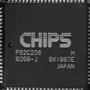
Pins 12 and 32 are the first and last pins on the bottom edge of the chip,
pins 74 and 75 are the 2 corner pins on the upper left corner.
OPTi F82C206
This is a small rectangular PLCC chip usually soldered onto the board.
CMOS RAM is cleared on this chip by shorting together pins 3 and 26 on
bottom edge of chip for a few seconds.
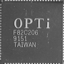
Pin 3 is third pin from left side and pin 26 5th pin from right side,
both on bottom edge.
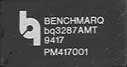
Dallas DS1287 and benchmarq bp3287MT
CMOS RAM can't be cleared. Instead you can replace RTC chip with a new
one. You can even use an updated version (DS1287A or bq3287AMT) which
support CMOS clearing.
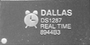
Dallas DS1287A and benchmarq bq3287AMT
This battery should last up to 10 years. Any motherboard using these chips
should not have an additional battery. CMOS RAM can be cleared on the
DS1287A and bq3287AMT by shorting pins 12 (GND) and 21 (RAM Clear).
Pins are labeled 1 to 24 running counter clockwise starting left of bottom
edge. Pin 12 is first pin from right side on bottom edge and Pin 21 is
third pin from left side on top edge.
Motorola MC146818AP or compatible
This is a rectangular 24-pin DIP chip, usually in a socket. Compatible
chips are made by several manufacturers including Hitachi (HD146818AP)
and Samsung (KS82C6818A). The number on the chip should end in 6818. Although
this chip is pin-compatible with the Dallas 1287/1287A, there is no built-in
battery. This means that CMOS RAM can be cleared on this chip by just
removing it from the socket for a few seconds and replacing it.
Dallas DS12885S and benchmarq bq3258S
CMOS RAM is cleared on this chip by shorting pins 12 (GND) and 20. Even
shorting pin 12 (GND) and 24 (5.0V) will help.
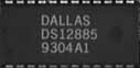
Pins are labeled 1 to 24 running counter clockwise starting left of bottom edge. Pin 12 is first pin from right side on bottom edge and Pin 21 is third pin from left side on top edge. Pin 24 is first pin from left on top edge.
![]()
Works with the following BIOSes
Acer/IBM 1.3
AMI BIOS 1.0
AMI WinBIOS (12/15/93) 1.4d
AMI WinBIOS 2.5 1.0 & 2.7
AMI Bios ? 4.2
Award 4.5x 1.0 & 1.4c & 2.3 & 2.8 & 2.9
Award Medallion 6 3.1
Compaq (1992) 1.0
Compaq 1.4 & 3.0
Phoenix A08, 1993 1.0
IBM (PS/2, Activa ...) 1.3
IBM Thinkpad boot pwd 1.5
IBM 300 GL 1.5
Packard Bell Supervisor/User 1.4
Phoenix 1.00.09.AC0 (1994) 1.0
Phoenix 1.04 1.4
Phoenix 1.10 A03/Dell GXi 1.4c
Phoenix 4 release 6 (User) 1.6 & 2.2
Phoenix 4.05 rev 1.02.943 2.6
Phoenix 4.06 rev 1.13.1107 2.6
Gateway Solo - Phoenix 4.0 r6 2.4
Toshiba 2.1
Zenith AMI 1.5
Typical Usage for DOS and all Windows users
1) Identify your BIOS manufacturer (usually displayed at boot-up)
2) Start in DOS, or start a DOS session in Windows 95/98/ME. For Windows
NT or Windows 2000 boot from a DOS or Windows 95/98 boot disk (you can
find boot disks at www.AnswersThatWork.com), and run
CMOSPWD from your boot floppy (or another floppy).
3) C: [Enter]
CD\CMOS_Pwd [Enter]
4) Type CMOSPWD at the DOS prompt and press Enter.
5) CMOSPWD will display a list of possibilities. Use the possibilities
itemised against your BIOS manufacturer.
Remember :
a) For AWARD BIOSes, use the Numeric Keypad (with NumLock ON).
b) AWARD 4.50PG BIOS always accepts "AWARD_SW", or "d8on",
or "589589".
c) Old Phoenix BIOSes will accept "phoenix".
6) If the standard method does not work, then try to kill the CMOS password
with CMOSPWD /K (and press Enter), and then see if you can get into the
CMOS without a password. If you can, you successfully "killed"
the old CMOS password. DO NOT KILL THE CMOS on IBM ThinkPad 765 laptops.
7) If you cannot kill the CMOS with CMOSPWD, then try the following, all
done from the DOS prompt of real DOS or of a DOS session :
DEBUG [Enter]
O 70 2E [Enter]
O 71 0 [Enter]
Q [Enter]
(The first character of each line above MUST be a letter, so whenever
you see "O", read it as the letter "O" and not the
digit ZERO, "0").
General Usage (List of commands)
cmospwd [/d]
cmospwd [/d] /[rlw] cmos_backup_file restore/load/write
cmospwd /k kill cmos
cmospwd /m[01]* execute selected module
/d to dump cmos in ascii and scan code
/m0010011 to execute module 3,6 and 7
Keyboard:
/kfr French AZERTY
/kde German QWERTY
default is US QWERTY
Platforms
- Dos-Windows version
Well, ... it works!
- Linux && BSD version
Users can work on cmos backup but they need root priviledge to
use ioperm function to have full access to cmos.
- Windows NT, W2K, XP
Users can work on cmos backup. To work on cmos memory, gwiopm need to
be
installed and running.
gwiopm gives direct port I/O access for specified ports to user-mode process
(ring 3) using Ke386SetIoAccessMap and Ke386IoSetAccessProcess kernel
functions.
1- You need administrator priviledges to install this driver
"instdrv gwiopm c:\tmp\gwiopm.sys"
(To remove the driver, run "instdrv gwiopm remove".)
2- Start the service if needed with "net start gwiopm"
3- Run "Cmospwd_nt /w cmos_backup"
4- Run "Cmospwd /l cmos_backup"
Laptops
On laptops, the password is usually stored in an
EEPROM on the motherboard, you need an EEPROM programmer (electronic
device) to retrieve it.
Acer 630: EEPROM 93c56 ?
Compaq M700: EEPROM 24C02
Dell Inspirion 7500: EEPROM 24c164
Dell Inspirion 8100: EEPROM 24c02
Dell Latitude C600:EEPROM 24c02, password in scan code at 0x00, 0x10 and
0x90
Dell Latitude CPI: EEPROM 24c02, password in scan code at 0x00, 0x10,
0x80
IBM Thinkpad X20: EEPROM 24RFC08CN, password in scan code at 0x338
IBM TP 380Z: EEPROM 24c01, password in scan code at 0x38 and 0x40
IBM TP 390: EEPROM 24c03 (be careful, there are two eeprom)
IBM TP 560X: EEPROM 24c01, password in scan code at 0x38 and 0x40
IBM TP 570: EEPROM ?, password in scan code at 0x338 and 0x3B8.
IBM TP 755CX,760C,765D: EEPROM 93c46, password in scan code at 0x38 and
0x40
IBM TP 770: EEPROM 24c01
IBM TP 600E, T21, T23: 14 PIN 24RF08
IBM TP T20: 24RF08, password in scan code at 0x338 and 0x3B8
HP Omnibook 2100,4150,7150: EEPROM AT24c164, 0x6D-0x7F area, unknow algo
put a 00 at 0x7F to clear admin password
HP Omnibook 6000: EEPROM 24c08 or 24c164 0x50-0xBF area
(maybe 0x50-0x6F only), unknow algo
HP Omnibook 6100: EEPROM 24c08
HP Omnibook XE3: EEPROM 24c16
HP Omnibook 770x: EEPROM 24c01
Sony pcg-fx950: EEPROM 93c46 ?
Toshiba 74600C: EEPROM 93c56
You can get/buy EEPROM programmer in electronic shops or labs, you need
another PC to use it.
You can desolder the eeprom with hot air or you can try to "clip"
the EEPROM. With the EEPROM programmer, backup your EEPROM and run "cmospwd
/d /l eeprom_backup". If you don't see the password, you can try
to fill the EEPROM with zero or FF, don't forget the reset the CMOS.
Toshiba
Differents passwords give the same 32-bit CRC,
so CmosPwd can only give one of them.
To reset the password of an old Toshiba, you can use KeyDisk. (cf my web
page)
If this doesn't work, you can try to build the Toshiba Parallell loopback.
To make a simple device that you connect to your parallell port, a lot
of
Toshiba computers remove the password when you boot it up.
The device, named "loopback" by some, could be made out of any
parallell wire with 25pins connectors (db25). You should connect
these pins: 1-5-10, 2-11, 3-17, 4-12, 6-16, 7-13, 8-14, 9-15, 18-25.
A db25 looks like:
1 13
_______
\_____/
14 25
Divers
- Award 4.50PG
There is an universal password AWARD_SW.
(d8on, 589589 ... works too)
- Award
Differents passwords give the same 32-bit CRC, so CmosPwd can only give
one of them. Use the numeric keypad.
- COMPAQ LTE 5300 notebook
Tolga Sinan Guney: there is a reset jumper on the motherboard
- DIGITAL PC300, Phoenix 4.0 Rel 6.0,0
Rene Pocisk: cmospwd /k works
- Fujitsu ICL
aksion: passwords are stored in EEPROM
- Phoenix
There is a backdoor in old version of Phoenix BIOS, the universal password
is "phoenix".
- Siemens Nixdorf
PCD-4ND, Michael: You can clear the password of this phoenix 1.03 with
"cmospwd /k"
Scenic Mobil 700, Josef Benda: "cmospwd /k" works! Phoenix Note
BIOS v4.0
Scenic Mobile 510AGP, Bernd: "cmospwd /k" works! Phoenix 4.0
R6 Version 3F31 dated 9.2.2000
What to do if you can't use cmospwd to clear your cmos ?
You can use debug to reset cmos CRC stored at 0x2E-0x2F
debug
-o 70 2E
-o 71 0
-q
What to do if cmospwd don't work on your PC ?
Try to clear password with cmospwd /k.
If cmospwd /k doesn't work, password is stored in an EEPROM. Try to find
a reset jumper on your motherboard or contact your PC vendor. If it works,
I can try to discover how passwords are encrypted.
I need to know what Bios you used and some cmos memory backup with their
passwords. (cmospwd /w backupfile) For passwords, choose
- some 1 and 2-letter passwords
- BBBBBBB
- BBBBBBC
- BBBBBCB
- BBBBCBB
- BBBCBBB
- BBCBBBB
- BCBBBBB
- CBBBBBB
Special Thanks to:
- Philippe Garcia-Suarez (AMI Zenith, IBM Thinkpad)
- Mark Miller (AMI WinBIOS)
- Ian Sharpe (Award 4.51PG)
- Darren Evans (Phoenix 4 release 6)
- Teun van de Berg (bug report for "cmospwd /w")
- Giovanni (IO access under NT)
- Robert Rafai (Dell Latitude)
- Guillaume Letessier (Toshiba)
- hackvenger (Phoenix 4.0 realase 6.0)
- "P. MADRE" (Award 4.51PG)
- SerbianHacker/Sasha Miloshevic (IBM ThinkPad 770)
- Michael (Siemens Nixdorf PCD-4ND, Phoenix 1.03)
- w0rm (Phoenix a486 1.03)
- Olaf Freyer (Phoenix 4.05 rev 1.02.943, Phoenix 4.06 rev 1.13.1107)
- Peter "Bluefish" Magnusson, author of !BIOS
- Tjiq (User password of AMI WinBIOS)
- Jedi (Award 4.51PG)
- Michel Creppy from Le Software Man
- YOGESH M (Award 4.51PG)
- Quattrocchi Stefano (Compaq DeskPro)
- Pencho Penchev (Award Medallion 6.0)
- Ernst Oudhof, bug correction for MODE_RESTORE_FORCE
- Lewis Hadley (Award 6.0 Medallion)
- Philippe Biondi (another AMI BIOS)
- Tompa Lorand-Mihaly (AMI Bios ver. 1.08 AN 1994 and Award 6)
- Jose Velasquez Villegas (ThinkPad 560x)
- bre786 (IBM ThinkPad T20)
and to all the guys, who provided information about cmos and reported
bugs.
gwiopm has been written by Graham Wideman (http://www.wideman-one.com/).
instdrv comes from Microsoft NTDDK.
!BIOS is a PC BIOS Security and Maintains toolkit, which includes various features to backup BIOS settings, recover passwords, to do direct modifications of your BIOS setup. This "how-to" attempts to explain all
mayor functions in !BIOS. !BIOS official site is http://www.11a.nu/
!BIOS is designed to be executed in a pure MS-DOS environment, but it works on most Windows95 and 98 setups as well. (If these operating systems aren't an option to you, I sugest you have a look at CmosPwd by Christophe Grenier, http://www.esiea.fr/public_html/Christophe.GRENIER/)
Development is mainly done by Bluefish (bluefish@11a.nu) and contributors are discuss the development in the ibiosdev mailinglist (for more information, check www.11a.nu). A special thanks goes to Cristophe Grenier
for aid and opinions, and to everyone who has participated in the development. A more complete list of contributers are available in other parts of the documentation. Be sure to read all documentation, most of it
is usefull.
PART II. Basic features
1. The user interfaces
When !BIOS is started, if checks if any parameter is passed from the command line interface. If not, it starts an menu system which most people find easy to use so I won't explain it any further.
However, try starting !BIOS with a command-line option, like:
IBIOS.EXE HELP
and if the option isn't recognized, it will give you all available options.
Do note that although we put some work into this interface, the menu system receives more debugging and contains more features.
2. The password crackers
The password crackers attempts to recover, decipher, the stored passwords. Due to the design of the chipsets and the BIOSes, the output of !BIOS typically assume an american keyboard. Because of that, if your keyboard is mapped in an none-american way you may experience that you have to think of pressing the key where it should be IF YOUR KEYBOARD WAS AMERICAN. As an example, several keyboards have moved underscore. German keyboards also switches X and Y. Additionally, you could try entering numbers on the keypad if the numbers above the letters doesn't work.
ADVANCED USERS TIP: The strings cracker shows the entire "CMOS", both as ascii and as scancode. If !BIOS doesn't decipher your password the passwords might be shown here in cleartext.
3. Backup and restore of CMOS/NVRAM
By using these features, you can backup and restore CMOSes. It can be usefull to do this before trying something you aren't sure will work, or if you suspect your CMOS has some kind of problem (old batteries in old computers, as an example)
ADVANCED USERS TIP: If you know of two computers with the same BIOSes, backuping CMOS from one where you know the password and restoring it on another will most likely copy the password.
ADVANCED USERS TIP: A backup of a password can be used together with the "sandbox" which offers remote work with the BIOS. Almost all features in !BIOS can be used remotely. CMOS backups are often important when inventing new password crackers.
4. Blasters (command line option WipeCMOS)
These tools attempts to make the computer think something is wrong with it's BIOS settings. This usually causes a panic and the BIOS removes password checks.
WARNING: There is no way of telling WHAT this will cause. All these blasters does what they are supposed to on SOME computers. It may make your computer unusuable. Don't come crying if you brake something with it.
PART III. Advanced features
Unless you understand
these features, don't bother using them.
1. Bios dump
This is an feature aimed at advanced users and developers. It copies a
part of the RAM dedicated to BIOS to a file. Most likely this will be
a part of the flash/rom, and may be a usefull aproach to reverse engineerers
who
cannot get hold on a flash update.
2. CMOS Editor
This is more or less an hex editor which allows you to modify all 128
bytes of the CMOS/NVRAM. It actually contains a number of neat features,
you can easily modify single bits with it, enter decimal or hexadecimal
numbers etc. Once you're done, you ought to "Calculate XXXX checksum".
Search the net for the latest CMOS.LST (included in Ralph Browns interrupt
list) for additional aid.
3. Sandbox
This feature is to be used with CMOS/NVRAM backups. It allows you to load
CMOS backups into !BIOS and it will then act as if the file loaded was
the actual CMOS. This should prove to be an great aid to a number of people,
as it allows users and developers to simulate another computer.
The sandbox is also present in the command line interface, try e.g.
IBIOS.EXE Sandbox CMOSAMI.BIO CrackAMI
4. Envrionment variables
!BIOS looks for two MS-DOS variables in the environment, These may simplify
debugging and can also be used to speed up the executation of !BIOS. If
you would run out of environment space, add "SHELL=C:\COMMAND.COM
C:\ /P /E:4096"
to your CONFIG.SYS and reboot.
Environment IBIOSDEBUG
If this variable is set to anything, !BIOS will wait for
user to press any key before starting the menu-system. Thus
developers can look through startup messages.
Environment IBIOS
A bitmask variable where each bit corresponds to disabling
one feature. It will allow developers to temporarily remove
features without modifying the source, or advanced users
to remove "slow" features
(antivirus check is slow on some floppies, as an example)
SET IBIOS=0 Default, same as
IBIOS not set
SET IBIOS=255 Maximum speed, all features
disabled
So far, the IBIOS environment can disable AV-selfcheck, Alpha
version messages, WinNT/multitasker detection, and finally
the Logo and fade (logo and fade is otherwise only shown
if !BIOS can find BIOSLOGO.RIX)
Special thanks
to: Chris Hare - chare@erols.com
 (C) All Rights Reserved. RASIKA CREATIONS (PVT) LTD - Moscow 2004-2006
)